Human Powered Vehicle Design Team
In the pictures above you can see various tasks being done such as laying up carbon fiber, applying filler, and preparing the mold for vacuum bagging. Although most of the pictures exhibit the latter stages of my design process, i.e. modeling, testing, and iterating, there is much more that goes on. The first few months of the year involved more focus on the brainstorming and planning stages. Not to mention the brainstorming that is done after current designs end up falling short of expectations. There is also aspects of research that help identify the contributing factors. For example, I was responsible for a computational analysis of NACA 6-series airfoils.
Airfoil Analysis

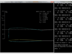
A pressure profile of an airfoil as displayed when XFOIL is run.
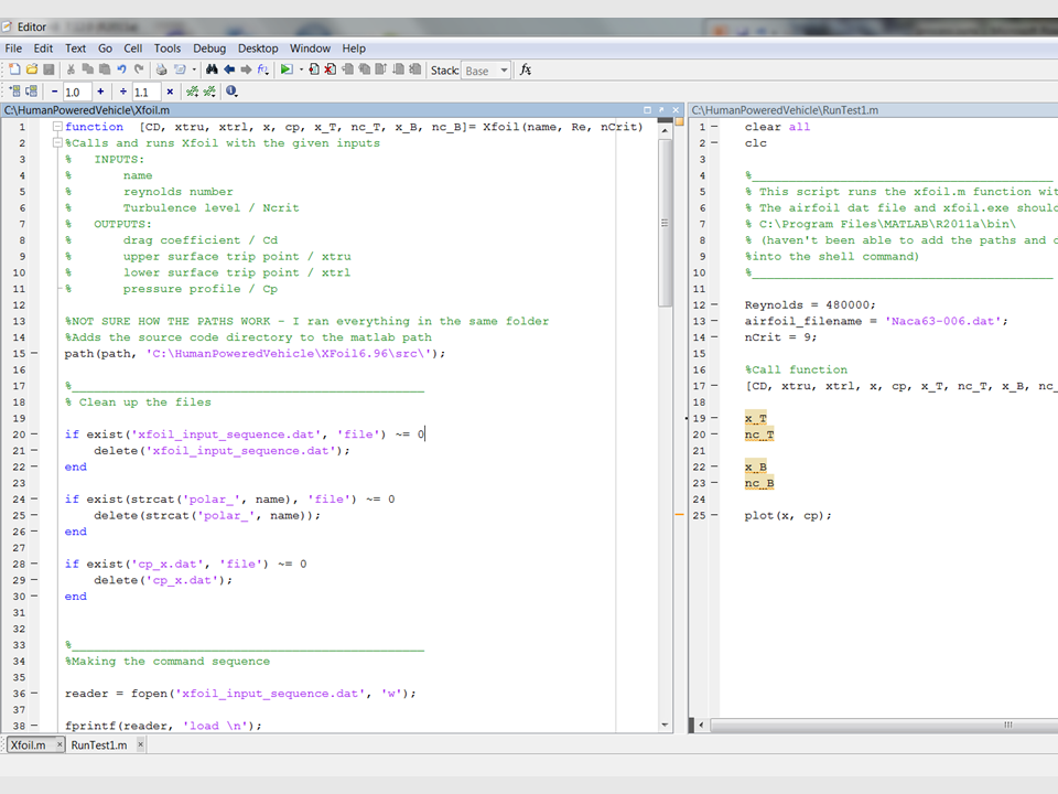
This project involved writing code in MATLAB to call XFOIL to analyze the airfoils. Specifically my script takes in an airfoil name, Reynold’s number and a turbulence level (nCritical). It calculates and stores the drag coefficient, upper and lower trip points and the pressure profile with a zero degree angle of attack. It also plots the amplification ratio and saves the frequencies at which laminar flow trips at. Currently this code is being used to determine what is the ideal shape based on the conditions the vehicle experiences. This research may influence the design of the wheel spokes and will eventually move to physical models for empirical analysis.
Testing and Analyzing
Many of the parts of the bike are made for the purpose of testing and gaining experience in the procedure. We repeat the process multiple times until we have found the parts that satisfy the evaluations we perform. For example, closer to the beginning of the year a roll cage was constructed so we could load it until failure. This influenced the design we chose for the bike.


